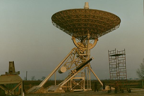
15 m Radio Telescope

Observer's
Handbook
Edited by:
K.M. Borkowski
Centre for Astronomy
Nicolaus Copernicus University
Torun Radio Astronomy Observatory (TRAO)
Toruń — Piwnice 2004
Table of contents
 1 Introduction to RT15
 2 Coordinates and specifications
 3 Preliminaries to observations
 4 Radio telescope control
   4.1 Invoking the steering program
   4.2 Steering commands
4.3 Commanding from schedule file |
1 Introduction
The construction of the 15 m radio telescope, based on design by a team
led by eng. Zygmunt Bujakowski, MSc, commenced in Spring of 1976
and was completed in October the same year.
The commisioning of the telescope was
followed by practical involvement of the TRAO in a most advanced
international observational technique,
Very Long Baseline Interferometry (VLBI). Our first interference
fringes were seen on the baseline to the Effelsberg (Germany) antenna
during correlation of observations made at the frequency of 5 GHz
on May 31, 1981.
Since then the telescope has been regularly used in VLBI
observations with the Mark IIc data acquisition system and
a rubidium standard as local oscillators frequency reference.
Occasionally, other types of observations were being carried out.
These included, for instance, monitoring of stronger pulsars
(Borkowski
et al. 1983).
When the 32-m
radio telescope came into existence and took over the burden
of VLBI observations, the 15-metre antenna was essentially relegated
to educational purposes apart from a few scientific programs.
Between January 1997 and June 1998 it was used for receiving
telemetry data from the POLRAD, a Polish experiment aboard the
Interball2 satellite.
Later (since February 2000 until end of 2001) the antenna was engaged
in spectral observations of a special type of solar bursts (so called
narrow-band spikes) in a 1420 MHz band (Dąbrowski et al., 2002).
2 RT15 coordinates and specifications
In the table below antenna coordinates
(Borkowski
and Bååth 1992) are formally expressed
in the IERS Terrestrial Reference Frame. The coordinates
are those of the point where the antenna polar axis crosses the plane of
declination axle. Using the IAU Earth figure ellipsoid (major axis of 6378140 m
and flattenig of 1/298.257) and applying suitable conversion formulae one
obtains these numerical data describing the antenna reference point:
|
| x, equatorial component at λ = 0°
| 3638609.62 |
± 0.19 m |
| y, equatorial component at λ = 90°E
| 1221773.23 |
± 0.54 m |
| z, polar component (φ = 90°)
| 5077024.50 |
± 1.66 m |
| Radius vector |
6364619.98 | ± 1.42 m |
| Geographical East longitude |
18°33'39.72" | ± 0.03" |
| Geocentric latitude |
52°54'37.93" | ± 0.03" |
| Geodetic latitude |
53°05'43.79" | ± 0.03" |
| Hight above the ellipsoid |
112.35 | ± 1.43 m |
|
| |
(Note that for most of practical, and astronomical in particular, purposes
the geodetic latitude is the quantity of prime interest, not the geocentric one.)
15-metre radio telescope specifications
| Type | steerable parabolic antenna |
|
|
|
| Reflector diameter d | 15.0 | m |
| Focal distance f | 4.9650 | m |
| Focal ratio f/d | 0.331 |
| Dish depth H = d2/(16f) | 2.8323 | m |
| Subtened angle 2Θo = 4arctg[d/(4f)] | 148.2531 | ° |
| Total surface area
8πf2[cos–3(Θo/2) –
1]/3 | 199.92 | m2 |
| Aperture (collecting area) πd2/4 | 176.71 | m2 |
|
Equation of the parabola*
| r = 2√{f(f – z)}
= 2f tg(Θ/2) |
|
| Focus to declination axis distance |
5.9097 | m |
| Declination axis to polar axis distance |
3.250 | m |
| Polar axle inclination |
53°5'43" |
| Maximum height (in absence of focus box) |
17.478 | m |
| Accuracy of reflector surface (rms) |
2 | mm |
| Accuracy of pointing |
0.01 | ° |
| Speed (both axles) |
0.25 ÷ 25
| °/min | |
| Declination range |
–32
÷ +97 | ° |
| Hour angle range |
–6h12m ÷ +6h12m | |
| Acceleration (average) |
~1 | °/s2 |
| Total weight (without counterbalance) | 45 | t |
| Number of panels (24 + 4 + 1) | 29 |
* r is the distance from
telescope symmetry axis, along which the z-coordinate is measured. The latter
has origin in the focus and is positive towards the paraboloid vertex. Θ is the angle between the z-axis and the radius vector.
|
3 Preliminaries to observations
• In the cabinet under the telescope
check computer date and time (the Universal Time must be set, not
the zone time). If necessary, set these parameters with the DOS commands
date and time. Then switch on the power supply and unblock
both the axle drives (motors).
• RT15 pointing setup
Before each observing session, besides the date and time, check also
proper adjustement of coordinate counters, since errors (not rare coarse
errors, e.g. a multiple of 1 degree) result in systematic loss of signal
in entire session. If after the power on both the controls of fine adjustment
(the two lower LEDs, which switch on for a short time with every crossing
of an integer degree marker placed around corresponding axle) are on,
and those of coarse
adjustment (the two upper LEDs, indicating region close to the RT15 base
position) are off, it means the telescope stays in the base position.
If this is not the case, one need to block the telescope movement,
reset the steering to manual mode (the R state of the switch
by the cabin wall). Then unblock the drives and manually move the
telescope (using the W-Z [E-W] or N-S switch and speed knob) in the axle
of interest until while the upper LED is off, the lower one is on.
In this base position the digital indicators of coordinates should
display these counts:
358.635
and
51.150
(hour angle and declination, respectively, in degrees). If they differ from
the above numbers considerably, say by more than 0.01), one must key in
the correct values using a special device (the small plastic box with 11
buttons and a cable terminated with the 25 pin connector). To this end, connect
the device to the corresponding connector (placed just below the declination
digital display) and press one of the last two buttons on the box (the left
button is for hour angle and the right one for declination).
Now revert to computer (automatic) control by setting the mentioned switch
from the R state back to A state (the letter A stands for
Automated, and R for Ręczne, i.e. 'manual' in Polish).
•
Each computer controlled observing run should end with the telescope in
the base position. In case of emergency, stop telescope control from
a schedule file and move manually the antenna to its base position,
then block the axle drives and switch off the power.
4 Radio telescope control
The entire steering system, in its present form, has been written
in the C programming language by
Eugeniusz Pazderski.
4.1 Invoking the steering program
Before execution of the steering program one should make sure
that the system time and date are identical to the Universal
Time (e.g. as indicated by the GPS clock in the control room).
In case of differences, use oparating system commands time
and date.
Using the computer in the RT15 cabin
The steering program can be executed under the DOS with the command
The program firstly reads the rt3.cmd file, which contains
initialization commands, then waits for the minute pulse of the computer
clock and then fully loads itself within 15 s. An operator now
switches power on and unblocks the telescope drives. After observations
are done and the telescope moved to the base position, the drives
mast be again blocked and power switched off.
Using the computer in control room (trao2)
Log onto one of computers with the Unix operating system as user oper
(a password will be required!) and run the program in a hpterm window with
this command:
Now it is possible to exercise a control over antenna motion from
the keyboard. In order to perform observations according to commands written
in a schedule file plik, type
cd /temp/oper/rt3cmd
(in this directory should reside the schedule file), and then:
Equivalently, one might as well type
rt3load /temp/oper/rt3cmd/plik staying in another directory.
To break a schedule being executed from a file one must type
<Ctrl>c
and continue typing commands from the keyboard or load another schedule file.
Interrupt execution of rt3 with the
1
command typed inside the RT3 Command Module window.
4.2 Steering commands
Antenna motion commands
| ps α δ |
— track source with right ascension α
and declination δ [deg or h/d m s] |
| po Δα Δδ |
— offset in α and
δ in degrees
[range –9.9 ÷ 9.9] |
| pop r θ |
— offset given in polar coordinates: distance
r at position angle θ |
| pos n | — move from coordinates +offset to
–offset in n minutes (scanning) |
| pod | — nullify offsets |
| pp HA δ |
— move to given hour angle and declination (HA, δ)
expressed in degrees |
| pb | — go to base position; same as pp 358.635 51.150 |
| pser | — servicing position; same as pp 88.240 -22.160 |
| psd | — cancel any of the above commands |
| epoch year | — epoch of source coordinates of ps command |
|
Data acquisition and display
Data obtained from the total power receiver are collected in directories
bearing names composed of the day and month numbers (e.g. the
name 10VIII corresponds to 10th August) and files with names composed
of the hour number and the .dat extension (eg. 03.dat).
| addch n | — switch n-th A/D channel on |
| rmch n | — remove n-th A/D channel (switch it off) |
| samp m | — set sampling rate at m samples per second |
| inf m | — record time and antenna position in
the file every m minutes |
| sc n | — change scale of total power display
by factor of n |
| of V | — shift displayed signal by V Volts |
File commands
| lf file | — open working file file |
| sa | — record data from scan in frequency domain
in the file |
| sap | — record sky scan data in the file |
| cofi comm | — open control command file comm |
| end | — close the comm file |
Other commands
(Commands v... are meant to be used only by entitled persons!)
| comment text | — send text to standard
output (screen) |
| he | — help |
| vh V | — set V Volts at hour angle D/A converter |
| vd V | — set V Volts at declination D/A converter |
| vr V | — set V Volts at hour angle D/A converter for tracking |
4.3 Commanding from schedule file
The RT3 program can accept commands from a schedule file. The file may
include date and time of the command execution. In the absence of these
timing attributes the program executes a command immediately. The same happens
if the time given is earlier than the system time. After reading in all the
schedule file the program continues to accept commands keyed in.
Each schedule file must end with the end command.
Example:
| 24/08/1995 10:35:00 | ps 125.32 45.69 |
| 24/08/1995 10:40:00 | po 5.0 0.0 |
| 24/08/1995 12:43:00 | pos 5 |
| pod |
| pb |
| end
|
Note: The format of date and time data must follow exactly that given
in this example.
Further practical notes concerning usage of schedule files
- After issuing the ps command allow for time necessary for the
telescope to reach a requested position. 5 to 7 minutes should suffice
in any case, however usually it is much shorter.
- The time of execution of the ps command may indicate a moment
earlier than the time of opening of the schedule file. Be however reasonable
in this respect.
- The command end may be issued right from the keyboard, and in this
case it also terminates execution of commands from a file.
- A schedule file may be loaded from another disk, but then it must
be placed in the root directory of that disk.
File originally posted on 16 July 2004
| Last update 25 October 2004 | |