Data Acquisition Hardware
(Last updated: 2004.09.13)
General diagram showing placement of various devices in relation to the 32-m radio telescope is presented at the end of this page.
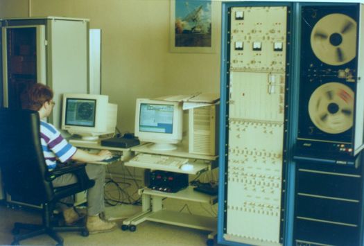
Very Longa Baseline Interferometry (VLBI) data acquisition is done with the terminal manufactured by the Penny & Giles (Great Britain). It is based on the VLBA design and consists of three main blocks: a set of 8 baseband converters (BBC), formatter and (tape and disk) recorder. The BBCs convert the intermediate frequency signal received from the telescope in the range 500 to 1000 MHz to the video band. Each converter has an LO (local oscillator) settable with step of 10 kHz and two (for upper and lower sideband; USB and LSB) filters 0.064 to 16 MHz in width.
|
|
| Fig. V.1a: VLBI terminal |
The formatter block converts analog signals coming from the BBCs to a digital form (one- or two-bit encoding) and passes them along with other important data to the recorder. The tape recorder is based on the Sirius Laboratory Data Recorder by the Penny & Giles, modified by addition or change of special read-write electronics, headstack similar to that of the VLBA terminal and installed on a special movable platform (capstan), and the VME controller.
 |
|
|
Presently (2004) the use of the tape recorder is being gradually replaced by more reliable disk recorder (Mark 5A recorder).
Internal frequencies of the terminal are synchronised to the Hydrogen frequency standard. Settings of BBCs, formatter and recorder are controlled through a computer (the HP PC Pentium 130) and an operating system, the Field System, which has been designed specially for the purpose. Detailed description of this device can be found in the documentation: Single/Dual Head Data Acquisition Recorder Rack Incorporating VME Control Rack, Penny & Giles Data Systems Ltd., Wookey Hole, Somerset (England), 1995.
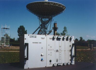
This device is detaily described in the 4-volume documentation Pulsar Machine. The figure below is taken from: Bryan A. Jacoby, A Broadband Receiver for High Frequency Observations of Radio Pulsars, Pennsylvania State University, 1997.
 |
| Fig. V.2: Some details of pulsar machine construction |
The correlator module has been constructed on printed circuit board (purchased). It was adapted to the CMOS technology in order that it could be controlled with a typical PC I/O card; only its signal inputs work in the ECL technology to ensure maximum speed. The highest working frequency of the spectrograph exceeds 100 MHz, but it was limited to 100 MHz because of properties of the digital samplers. This means that the maximum permissible bandwidth of the sampled signal is 50 MHz. However, the correlator board carries four similar sections, 4096 channels in each. Thus, using four samplers, it is possible to have an effective bandwidth of 200 MHz in the autocorrelation mode. In the cross-correlation setup the first two correlators in each channel work in the autocorrelation mode and the next two ones carry the cross-correlation.
32-bit outputs from the 16 384 channels are serially read (in 0.6 s) by the control PC. The PC does the necessary data processing and displays the results.
 |
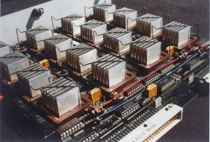 |
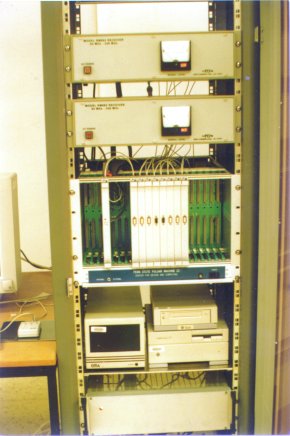
| Fig. V.3: Digital spectrograph: front view (in the background there is the 15-m telescope; left panel) and the main board inside with the sixteen 1024-channel correlators (right) |
The sampler module has been designed and built in the TRAO. It has four samplers working at a rate of 100 Msamples/second at their heighest. It is based in the ECL technology. Input signals are scaled so as to match the BBC outputs of the VLBI terminal. The samplers are essentially A/D converters, whose four logical output states are converted into three two-bit digits acceptable by the correlators. The sampler module includes also circuits that form and distribute clock signal, circuits of automatic zero voltage control, as well as a source of stable reference voltages (as sampling levels).
The clock synthesizer generates 16 signals of frequencies ranging from 1 MHz to 64 MHz with the binary progression, and an extra waveform of 100 MHz meant for the spectrograph work at its maximum speed.All these frequencies are phase-locked to a 10 MHz output from the Hydrogen maser. This module has been built in the ECL technology.
An industrial PC Pentium has 32 MB of RAM, 2,3 GB hard disk, two standard I/O cards and network card. It runs under LINUX operating system.
A cooling system is necessary because of high level of heat generated by the correlators (about 4 W per the correlator set, i.e. 64 W altogether). As an additional safety means there are temperature sensors which, in case of a fan failure, allow to switch off the power supply.
The power supply module consists of two standard PC modules, 200 W each, and specially made (in TRAO) power suppliers for the ECL logic (-5,2 V, -2 V) and the analog part of the spectrograph (±5 V).
 |
| Fig. V.4: Block diagram of the wideband spectrograph |
| Schematic diagram of RT32 devices |
 |