Receiving systems — S. Jakubowicz
(Last updated: 2004.08.22)
The task the receiving system is to carry, is to precisely measure an eloctromagnetic field intensity at or near the focus of an antenna. Each of the systems mounted at the RT32 secondary focus has been designed to ensure good illumination of the secondary focus, low level of intrinsic noise and conveniently wide bandpass. The systems were manufactured in the Department of Radio Astronomy basing on original designs and calculations. Components purchased have been indicated in the descriptive text that follows.
|
|
| Fig. IV.1: Block diagram of the receiving system for 1.5 GHz band |
The two signals coming from the transducer are transferred to a symmetric directional coupler by way of electrical coaxial cables (screened with stainless steel). The coupler allows for injection of noise calibration signals into both the channels. Then the signals go to cooled HEMT preamplifiers, manufactured in NFRA, the Netherlands. The preamplifiers are characterised by very good coupling to the transmission lines at the input and output, low intrinsic noise (5 K when cooled to 15 K) and wide passband. Their drawback is decreasing amplification with the frequency (about 5 dB per 500 MHz).
The directional coupler with amplifiers as well as the transformer are contained in a vacuum vessel made in the TRAO workshop. A cryogenic temperature is obtained with the Model 350 Cryodyne Refrigerator (Helium cooled) of the CTI-Cryogenics and the 1020R compressor (Fig. IV.5).
There are two diodes inside the vacuum vessel powered with a constant current. The voltage over them is measured as an indicator of the temperature.
The remaining components of the receiving system are placed in a thermostat. Each of the two signal channels includes a mirror frequency filter which determines maximum extent of the bandpass (1400 – 1800 MHz), insulator (made by Harris), second amplifier, mixer (Anzac), and intermediate frequency (IF) filters and amplifier.
The local oscillator signal for both the channels is supplied by the HP-83711A synthesizer of the Hewlett-Packard which can provide an output in the range 1 – 20 GHz. The sinthesizer is phase synchronized to an external reference signal at 10 MHz, which comes from the Hydrogen maser.
The user may remotely change the following parameters: observing frequency through change of the local oscillator frequency (the lof command), control the amplitude of the local oscillator signal (the lop command), control calibration signal level (the latt command), switch this signal on and off (the cal command), and read the diode voltage as a check of the temperature inside the vacuum vessel (the dewar 1 command). In the secondary focus cabin one may further check levels of power supply voltages and currents consumed by the preamplifiers.
 |
|
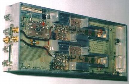
| Fig. IV.2: General view and part of HF electronics of the 5 GHz receiving system |
This receiver is connected to a corrugated feed with circular cross section, assuring a very good illumination of the secondary mirror. The output signal goes to a wideband polarizer (made by Atlantic Microwaves) cooled to 70 K. Both the polarization components are sent through short concentric cables to a symmetrical directional coupler enabling the calibration of amplitude by supplying noise of known power, and from there they go to preamplifiers (made by us in co-operation with the MPIfR). The preamplifiers have a flat bandpass profile, good impedance matching on input and output as well as very low noise temperature (5 K when cooled to 15 K). Their bandpass extends from 4,5 to 5,3 GHz. The directional coupler and preamplifiers are temperature stabilized at 15 K and are kept along with the polarizer in a vacuum vessel made of stainless steel.
 |
| Fig. IV.3: Block diagram of the 5 GHz receiving system |
The Helium refrigerator Model 350 (of the CTI) with the above described compressor 1020R provide cryogenic temperature of the devices in vacuum vessel. The cooling here is more indefectible than in case of the similar system at the L-band beacuse of a smaller mass and smaller surface of cooled devices.
Farther components of the receiver are placed in thermostatic box. Each of the two channells possesses a wideband insulator (by the Harris), second amplifier, microwave switch for a reference signal, third amplifier, two externally selectable filters of mirror frequency, fourth amplifier, mixer (by the Anzac), intermediate frequency filters and amplifier.
The source of the LO signal is the same as in the L-band, i.e. the HP-83711A synthesizer by the Hewlett-Packard. Inside the receiver, the LO signal is fed to a power divider. The signal from each of the two outputs of the divider is amplified and delivered to a corresponding mixer, one of the signals being shifted in phase relative to the other by 90°.
As in the L-band system, the operator can remotely control the observing frequency (through appropriate change of the LO frequency), adjust the LO voltage, switch on the calibration noise source and control its signal power. Additionally, he can change between two filters of mirror bands (command cfilter). The operator can also have displayed a voltage corresponding to the degree of cooling-down of the preamplifiers (command dewar 2). Some more parameters (power supply voltages and currents of each of the HEMT transistors) can be read directly at the receiver in the cabin of secondary focus.
 |
| Fig. IV.4: Block diagram of the 6.5 GHz receiving system |
Inside the vacuum vessel there are two preamplifiers (TRAO production) of very low noise temperature (6 K) and wide bandpass (5 – 7 GHz), working at temperature of 15 K, as well as the above mentioned transformer. This low temperature of cooled elements is sustained by the Helium refrigerator Model 22 (by the CTI) and the 1020R compressor.
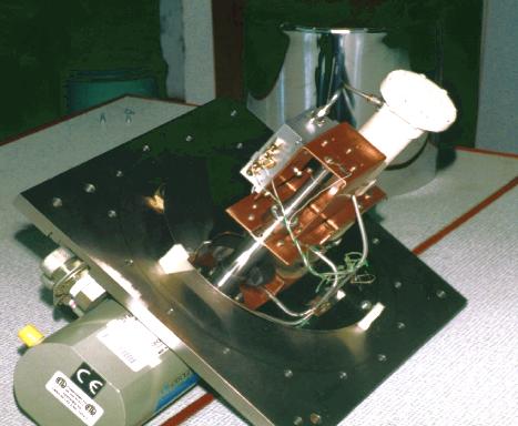 |
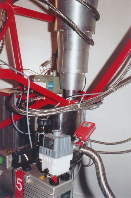
| Fig. IV.5: Cooling system (dewar with opened vacuum vessel) |
Each of the two channels of C2 receiver possesses a second amplifier,
a set of two (switchable alternately) filters of mirror frequency,
third amplifier, mixer (by the Anzac) and filters and intermediate
frequency (IF) amplifier.
The LO signal comes from the HP-83711A synthesizer (the same as employed in the L-band system). Similarly as in the C-band, this signal is split and phase-shifted to feed mixers in the two polarization channels.
Noteworthy is the fact that this high quality receiver has been designed and built by the TRAO staff based on newest technologies and elements. It excellently meets requirements of the present day radio astronomical observations in this frequency range.
| Basic parameters of receiving systems |
| |||
|
|
Fig. IV.6: Distribution of feeds at the secondary focus (shown
as seen from subreflector). ,,Offsets" (corrections in azimuth and
zenith distance;
roh command) are given in degrees (AKę) |